And gate CAD/CAM system research (a)
CAD technology application in all walks of life completely changed the traditional design patterns, created a huge social benefits and economic benefits. At present, CAD technology has from the pure painting-tool toward the integration of CAD/CAM stage design and manufacturing process, product support. According to statistics, product design and application of CAD technology factory after shorter period 1/3-2/3, improve efficiency, 3-10 times the rate of product design, manufacturing technology in the development of a large, modern manufacturing progress toward a step. However, the oil industry and the production of most factory gate products by half since long experience, half of the theory of traditional design method, product delivery performance and can meet the needs of customers, the influence on the market competitiveness of products.
Functional design
Gate valves CAD/CAM system should be facing the market, meet the customers' requirements, and to utilize existing achievements, using CAD/CAM system design and manufacture of integrated information for management information, provide backing, for businesses, and to lay CIMS. Therefore the future trend of development, according to the gate design CAD/CAM system is an open system based on network, and should have the following three functions.
1) optimizing design and finite element analysis function
Gate valves are designed in series model based on the modular design level, the design and calculation of complex requirements, high accuracy, wide application scope, so hand at home and abroad in recent years by the advanced scientific research and the new design calculation theory, improve the overall performance of the valve, gate valve upgrading of products, to meet the requirements of the customers, On the other hand using finite element analysis and optimization design of modern design method, the optimum processing capacity and establishing the efficient and practical structure analysis and design calculation of modules.
2 parameter design and automatic drawing function
Due to the change and connection form of different levels of stress, gate structure form is various, the user's requirements of different design parameters and structure change at any time. To ensure the advanced CAD system, practical using parameterized module, are mainly as follows:
(1) CAD system structure design
In order to improve product sophistication, reasonable distribution and utilization of resources, the gate of computer "variable" and "" two kinds of processing methods. The so-called "variables", refers to the design with different parts, such as the disc, seat such nonstandard. This part of the design parameters and the way of drawing automatically, computer automatic processing to determine the structure shape, size and size. "And" refers to the corresponding standard part library, to meet various graphic design needs
(2) parameter mapping subsystem
CAD system can automatically accomplish except for graphics, still can be determined in assembly parts in the position and size and automatic assembly relation with drawing machine, finally output design of a complete set of drawings. In this gallery are dynamic subsystem, including its core disc, seat and handle series etc. More than 20 different specifications of components to ensure the galleries, convenient and reliable at any time to complete gate assembly and components design and drawing.
3 CAM function
CAM module structure in parts, parts of the graph generating production, automatically generated CAM required data and process information, the structure of NC machining codes, automatically generated &fair standards, production planning, resources, and the design requirements of NC code NC simulation and development, in order to go before the sword of actual machining process and the tool path, avoid process simulation of various damage, realize the integration of CAD/CAM information.
System structure
To meet the above three functions, the gate of CAD/CAM system is divided into five modules.
1 design calculation module
Quote the world's latest theory and the advanced scientific research achievements, has more than 20 under an optimized algorithm of design platform, can make the original design of more than 20 days to shorten the cycle of about 30 minutes.
2 analysis module
Adopts the advanced MARC MARC company nonlinear finite element analysis of structure theory and method, and has established the advanced before and after processing function structure analysis module.
3) dynamic atlas module
To further improve the product's "three", "three" developed on the basis of the product, the level of intelligence in parameter design and parameters of the formation of gate gallery dynamic drawing.
4 CAM module
Using NC code technology and numerical simulation technology research of NC machine postprocessing procedures and the main parts of the NC code automatic generation, and through the simulation of NC code to ensure the quality and machining.
5 dynamic database
To represent each module, realizing the information between modules, real-time transmission, together with each module of CAD/CAM system.
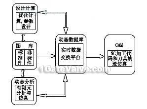
According to manufacturer's product structure and concrete requirements, the gate of CAD/CAM system structure is shown in figure 1. The design and calculation module of different specifications of the gate to solve the optimization design of components. Atlas contains module and into the national standard parts, and the standard library and reflect the characteristics of the gate of the graphics libraries. Database module design standards, responsible for store data and of graphic data management, and realizes real-time dynamic data exchange [5].
Gate valves CAD/CAM system working process and process information contact is as follows:
(1) using the optimized design module and finite element analysis module gate optimized structure analysis and design calculation, the structure and properties of valves parameters, and the design parameters in the database.
(2) according to the gate design, system structure parameters of automatic gate and parts of parameterized design and structure of automatic drawing, complete the rendering drawings, parts of valves in the system will automatically during the structural parameters of various parts in the database.
(3) completed the overall with pre-installed gate, and check the correctness.
(4) of the automatic gate structure parts and components manufacturing all kinds of automatic generation, and provide for the CAM of parts of structure and process information.
According to the process (5), CAM module instruction from a database of parts of removed, automatically generating process information structure of NC machining parts, NC code to the NC machining center code can be finished parts processing. As may be necessary to important parts processing code to check the simulation accuracy.