The gate of CAD/CAM system research (2)
Valve parts of parametric design
Gate valves belongs to many varieties and specifications, the serialization of products, each gate by nominal pressure into different series, existing 14, 21, 35, 70, 105, 140, 210, 400MPa eight series, a series of transmission mode, according to each connection form, structure form into different types, Each type and size is divided into different specifications according to size, Each valve is in 100 sets of drawing. Although the same class valves have different series products, the same series of products and divided into different types, but each kind of type of structure, size is different. A specific type of gate, holds a large scale, with standard 355.6 mm (14 inches) Z40H - 150 wedge type gate, for example: there are ten pieces, gb standard parts factory is a total of 21 November, standard, accounting for approximately 75% of the total number of parts, so using parameterized modeling design method can perform well in product design drawing working gate.
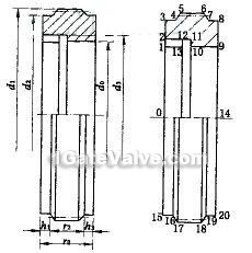
In Auto CAD R14 environment, use quadratieally development, develop a language can be directly articulated in Auto CAD menu tree parametric design module, it USES independent Auto CAD interactive environment to work all the parts model parametric design method, the model parameters are calculated the constraint relation between Auto CAD, after completion of the function design and drawing parts. Specific implementation, users will graphic design conditions and certain size (or constraint conditions) is associated with the size of the graphic design conditions as the function, when the design, graphic size will be updated accordingly, so the runtime input parameters (refers to a major decision gate parts of graphics, characteristic parameters of other dimensions that this parameter relation by the computer automatically calculate), the relationship between the size of graphic data and automatic design and drawing graphics. Figure 2 is parameterized design example, a seat in the parameters that are d0 r0 design parameters, and other related parameters, for these two parameters can be calculated according to the parameters, the design of control chart available seat basis and node technology draw.
CNC programming and simulation
System structure design, can according to the parts of the process design, process and provide geometric information automatically NC programming, and simulation. For CNC programming, should according to the characteristic of parts of the form to select roughing cut. System provides the horizontal roughing cut cycle, the longitudinal cutting circulation, rough outline roughing cut cycle three ways, user can choose according to the actual shape of parts of a kind of coarse cutting cycle. Then the system requirements of NC program storage user input file name, system recommended extension use * CNC.
In the NC program, the system will show the rough machining cutting depth and feeding and finishing limits.but for reference, if operators of the recommended that accords with the actual situation of the not too, can be modified, and can meet the requirements of the automatic generation process. The NC parts,
NC program, need to verify the NC machining simulation program correctness and effectiveness. This system is in blank by displayed on the NC program on route to the inspection of the tool path, the static and dynamic process before simulation. System providing static contour, static test (knife repairing trajectory real-time dynamic), three simulation form.
Static operator input trajectory simulation requirements contour line interval and graphics to control rod, the speed and size drawing, On the basis of static contour simulation tool radius, if consider cutting length and compensation of trajectory is cutting knife repairing trajectory of static inspection; Real-time dynamic simulation is fully simulate the real process of cutter center processing, the actual path exercise dynamically displayed on the screen.